
Hi there
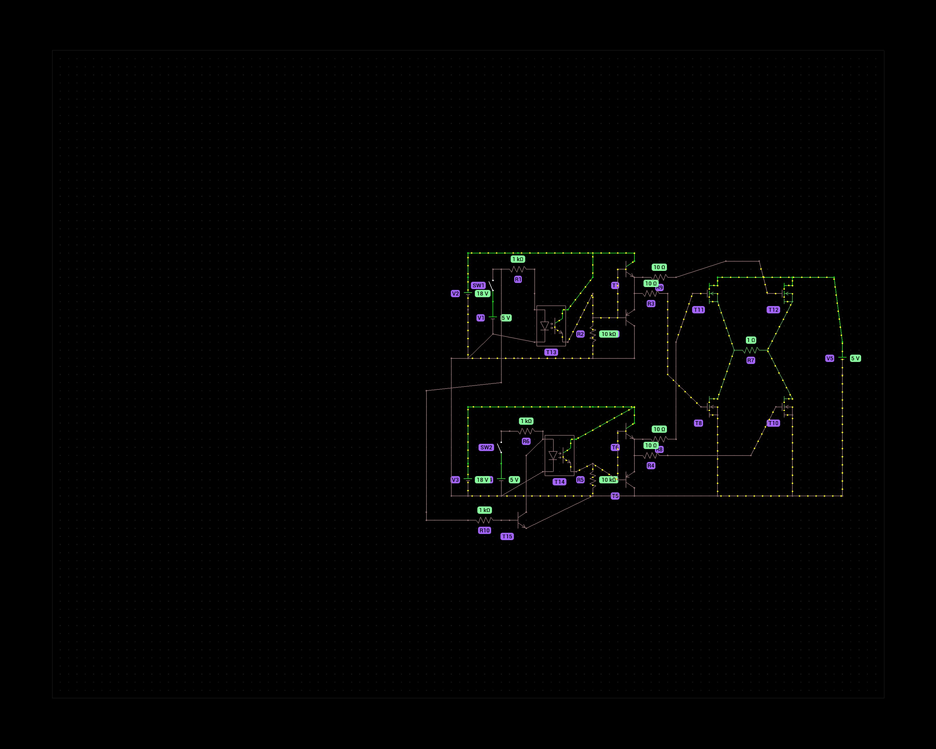
The purpose of this schematic is to control a DC motor that runs at 8V max. That is why I chose 4 N-channel mosfets in the H bridge. P-channels would not fully activate at voltages above -10Vgs but the N-channels can handle 18V at the gate.
The 5v switches represent an Arduino’s digital output pins. One to turn forward, one for reverse. To prevent a failure scenario where both pins are HIGH I added a transistor that prevents current from flowing through the optocoupler on the second half bridge.
Does this circuit make sense? I’m not an electronics engineer, just a hobbyist and have doubts about how effective the gate driving circuit is of the mosfets.
Thanks!
You must log in or register to comment.
Please don’t use non perpendicular lines and draw in a clearer software if possible. Its quite hard to read.
What is the point of the push-pull BJTs? With the optocoupler you could drive the nmos gates directly. If you need more current to drive the gates (unlikely for a small motor), I suggest you buy dedicated gate drivers. They are tested and not expensive. If you have the 18V available already, using the optocouplers directly would be a lot simpler.
This looks like the web simulator falstad…
Proto on Android.
Right, sorry about that. I made the simulation on my phone with the Proto app.
I figured the push pull part is good practice with mosfets. It’s partially the learning experience and if the motor stalls it could draw several amps.
I won’t be doing PWM, just on and off so maybe just the optocoupler is good enough.
I’d have to order dedicated gate drivers and have a lot of 547 and 557 transistors in stock at home.
In that case I would omit the extra transistors and use only the optocouplers.
What sort of application is this? Having 18V somewhere and a 5V supply too that can output several amps is quite unusual.
Thanks again for the advice. I made a working prototype and attached it to my pump. The PCB is also made at home which is something I’m trying to learn.
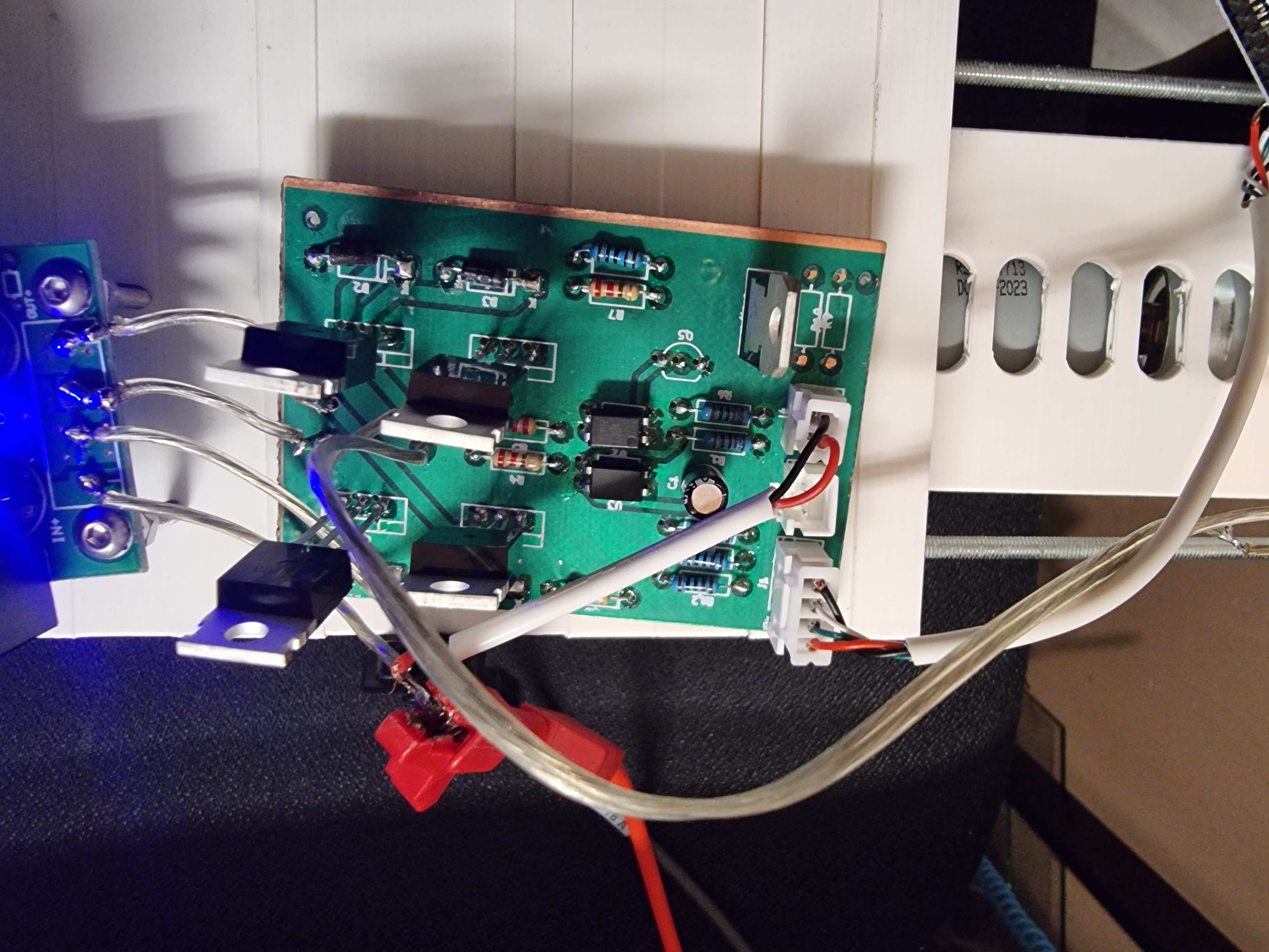
For now I’ve used just optocouplers to drive the mosfets, since pulling p-type gates down to above -24V seemed like a hassle. I’ve ordered some IR2210 gate drivers and intend to use those with PWM later to not have to use a buck converter.
Here’s a video of the pump. https://drive.google.com/file/d/1qKDBLTbYi2Fbu3UOXpxqSoj00oueWK-K/view?usp=sharing
And the pump in action. https://drive.google.com/file/d/1--HyeJGtYS5dgsjgelE6CrOm2vbBmwXU/view?usp=sharing This version has a stepper motor instead of a DC motor. Stepper motors have low speed limit which is why I’m trying to change it to DC motors.
No problem :) Let me know if you need any help!
Well, the whole setup is a semi automatic greenhouse. It has a 12 channel peristaltic pump, grow lights, heater and a plant shaker for pollination. I’m attempting to grow indoor tomatoes and chili’s. Not weed although I have learned a lot from weed growers.
The system runs on a 24V power supply so that is easily accessible. The 18V comes from an LM7818 and the motor speed will be regulated with a buck converter module.
I also worry about the LM7818. It drops about 6V, so at 330mA it burns 2W, which seems like the maximum for the package that I quickly pulled up. If you have a very efficient buck converter that gives you at most about 1A to drive the motor. Not a lot of overhead.
Also as I said already, you could just skip the whole thing and make everything work from the 24V using PWM. Since you want to drive it with an arduino that is not a difficult thing.
Good one. I haven´t considered that. The 7818 will only deliver current for very short bursts but perhaps that already is too much. I’ll look into the PWM solution.
If I were you, I would not step down the 24V, but use that to drive the motor with pwm. It requires a bit different H bridge but overall it would be simpler. But if you already have a converter module that is good enough this works too.
That would require an H bridge with two Pmosfets on the high side indeed. And a way to prevent the gate voltage from going below -20V on those.
The PWM frequency on arduino nano is also a bit slow for controlling a motor so a 555 circuit needs to be added then. I have a large amount of XL4016 modules that work well though.
Thanks for the advice!
I don’t think the PWM on the arduino is slow for your application. Motors are actually great for filtering. Even if the current is not filtered, mechanically it is so slow that you can go as low as 100Hz and still drive the motor acceptably well.
Looks fine to my eyes, but the last time i made a motor driver it caught fire so i wouldn’t take my word for it if i was you
Haha. I do not want this one to catch fire.
DC motors have high inductance, meaning that the current going over it will resist to change. When you turn off a pair of nmos, current will likely start flowing over the the other pair, from source to drain. Depending on the spec of your nmos, you may consider using diodes in parallel to nmos to carry this current. Obviously these diodes should be reverse biased during normal operation.
Are you trying to run your motor at 5v? that’s what it reads to me.
If your current draw is under like 700ma, Consider a bridge driver like the L9110, it’ll get you the with minimal effort. There are other drivers out there as well. https://www.adafruit.com/product/4489
Between 4 and 8V. I’m driving a pump with a 12V rated 775 motor. Running it at full power makes the pump go too fast and with a lot of noise.
It’s kind of an overpowered motor for this project but I have a couple of spare ones.
Is it okay that there is no stop state? It can only drive the motor in either direction, bit there is no OFF state with your inputs.
The off state is with both inputs at 0.
Obviously. No idea what I was thinking.