Me a few days ago, shopping on Amazon: “All the component and jumper wire leads are going to be on the bottom anyway; why shouldn’t I get a pack of single-sided breadboards for $6.25 instead of double-sided ones for $10?”
Me today, after having lifted three pads off the damn board in 10 minutes: “Oh, that’s why.”
Get the double-sided breadboards; they’re worth it.
The solder joints will be a lot stronger too. The solder will flow through the plated through hole and create a strong mechanical connection.
The pads shouldn’t be lifting off the single sided boards though. Either the boards are crap quality or you’re overheating the pads.
Either the boards are crap quality or you’re overheating the pads.
Or both, probably!
Yeah I’ve only seen lifted pads when I’m desoldering a huge component, or on the absolute cheapest board. I find that the white boards and orange boards always suck
Double sided perfboards way more often than not don’t have plated vias. The vast majority are just etched from a 2 layer blank without any post processing.
You would have to solder specifically on both sides in order to increase the strength.
But yes pads lifting is almost exclusively from dumping way too much heat in it. Because there is no plated through hole, it also has ~1/4 of the thermal mass so it is easier to overheat and damage the adhesive.
I guess the stuff I buy is an extra tier above then, because I definitely only spring for the platted through-hole double sided boards. I’ve cut little sections of my supply to use in various projects.
If your pads are lifting, you’re overheating the board.
A couple of tips that can help a lot.
Don’t underestimate the importance of flux. Cheap boards often have a lot of crap on the copper. Flux burns this off, allowing for quicker, better joints. Most solders have flux in them, some more than others. Beyond that, you can also buy rosin flux very cheaply. It’s amazing for cleaning up particularly bad, or sensitive, components.
Have confidence when heating. Most newbies tend to ‘dab’. They are scared to overheat the component or board, and so try to add a little heat at a time. This is actually FAR worse for heat. The heat spreads out into the components and glue, causing problems. Instead, you apply heat once. The iron stays in place until the joint forms. If you back off, you need to wait a few minutes until everything is completely cool to the touch. No tap-tap-taping.
The last point of note is to check your lighting. Most beginners struggle to actually see what they are doing. In low light, our pupils open up, to allow more in. This reduces our depth of field, and makes it harder to focus clearly. You want daylight levels of light on your workpiece. There are several apps that let you measure light levels. You might be shocked at how low it is. Multiple directional lights are the best option. You want it focused to maximise brightness, but multi source to avoid harsh shadows.
You might have figured out most of these, but hopefully, some of it will be of help.
the last one is so true, I never realized how dark my desk was until I tried soldering and couldn’t do shit without an extra desk lamp
What are double sided breadboards?
Perfboards?
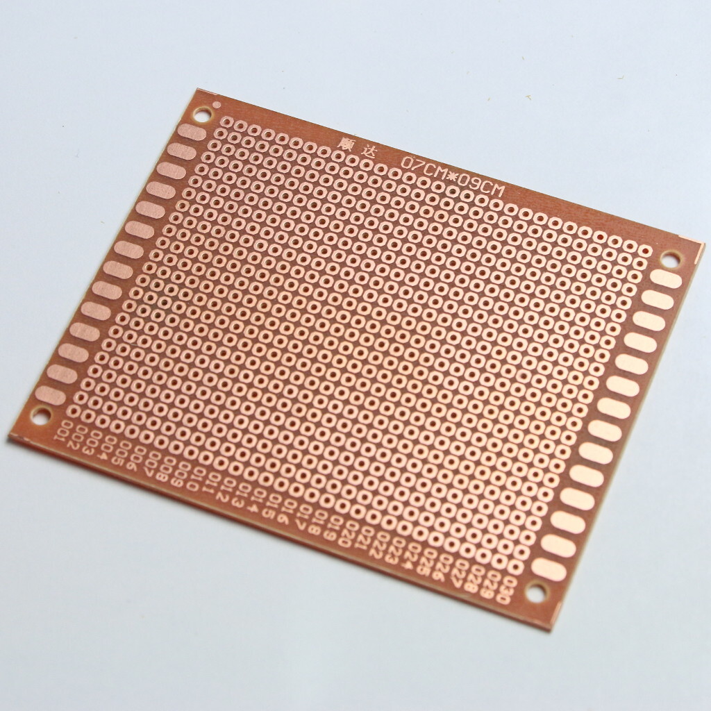
These can be double sided and can be soldered to.
Breadboads can only be one sided.
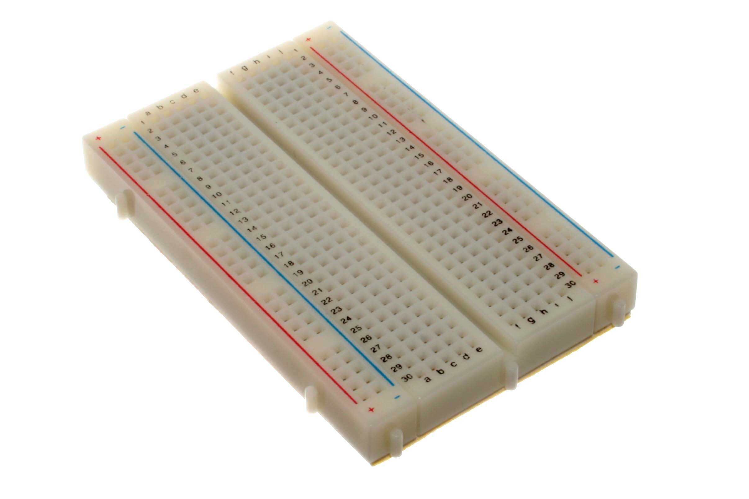
Edit: this is a solderless breadboard. Non-solderless breadboards do exist, as I learned today.
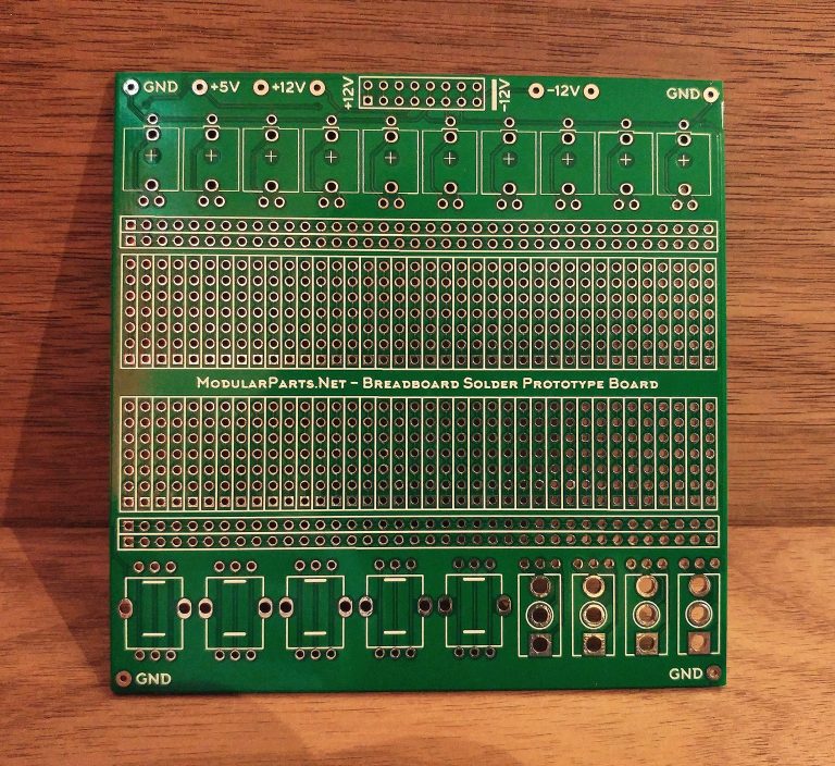
Thank you! I thought I was losing my mind.
Probably double-sided prototyping PCBs. The double-sided ones tend to be green (FR4 fiberglass resin), the single-sided orange (FR2 paper phenolic-resin).
Terminology varies, a lot of greymarket sellers use “veroboard”, “prototype board” and “breadboard” interchangeably.
The glue between the copper pads and the board itself tend to better with the double-sided boards, I agree with you OP :) Although this isn’t universal, I’ve had some nasty bare copper boards on FR4 where the pads pop off when you try to solder to them; and some old FR2 boards with really well adhered pads. I’ve read somewhere that this might (?) be due to moisture in the PCB boiling off when you put the soldering iron to a pad and that baking the board in an oven first can help, but I have not tried that. I suspect a lot of it comes down to the quality of adhesive used between copper and substrate.
They’re pretty much the same as a solderless breadboard, in that they have dedicated power/signal rails and multiple rows/groups of bridged pads. They are usually used for a working prototype, as opposed the solderless ones used for initial circuit design/debug on a benchtop.
Here’s a general design with dedicated in/output pads.
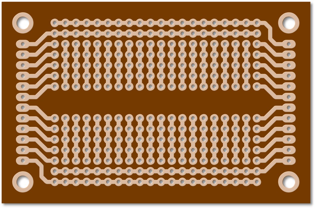
Presumably prototyping boards with plated thru holes.
Both sides have copper plating to wet solder to.
You can still lift pads on many double sided boards. The real key is to use the highest heat capacity iron tip that can fit into the task at hand. The highest heat capacity tip will allow you to lower the tip temperature and transfer that heat effectively. With experience, you'll also learn when to add supplemented heat due to ground planes and components.
If you ever get to the point of etching your own boards and then the extra even rarer step of attempting through hole plating. The biggest challenge is how to get the initial conductive bridge to form inside the hole itself. This usually involves something like a paint with graphite powder, or other chemical solution. Then the holes are electroplated with copper. The inside of these holes is not a particularly great surface to work with and has minor inconsistencies that are typical of a drill bit finish through a substrate like fiberglass. You’re likely to have a composite of different materials like the glass fiber and resin or even a plastic core with CEM. It does not make a very consistent substrate to coat, and the surface is hard to build consistently.
I come from owning an auto body shop twice, so I know all too well: liquid paints always pull away from sharp edges where they will be thinnest. Also, absolutely every finish is only as good as the layer it is on top of. If you put a $10k job on top of a pealing $500 job, it will fall apart and be nothing but problems within a year.
The qualities of the base coating that is used to initially bridge the top and bottom layers is what will largely determine the durability of rework.
Overheating the region will have a big impact on the outcome. With many stations and tips you’re likely to use too high of a temperature to compensate for tiny or the wrong tips. You need to get the lowest temperature possible and normalized on the whole connection quickly for rework. Preheating makes a big difference, as does eliminating any even small sources of moving air.
My favorite Hakko 900 series tip is the 900M-T-3.2D 4962615503139 (have it right beside me now in a sleeve of several). Genuine Hakko tips have far better plating that makes a difference too. I can do nearly every job with that tip turned in various orientations.
A hot air rework gun is helpful, just never cut off the cool down time prematurely. You can get a couple of the fake magic arm camera clamps for photography to make a handy holder for a cheap hot air rework setup. Use the counter clamp from the second arm to hold the gun.
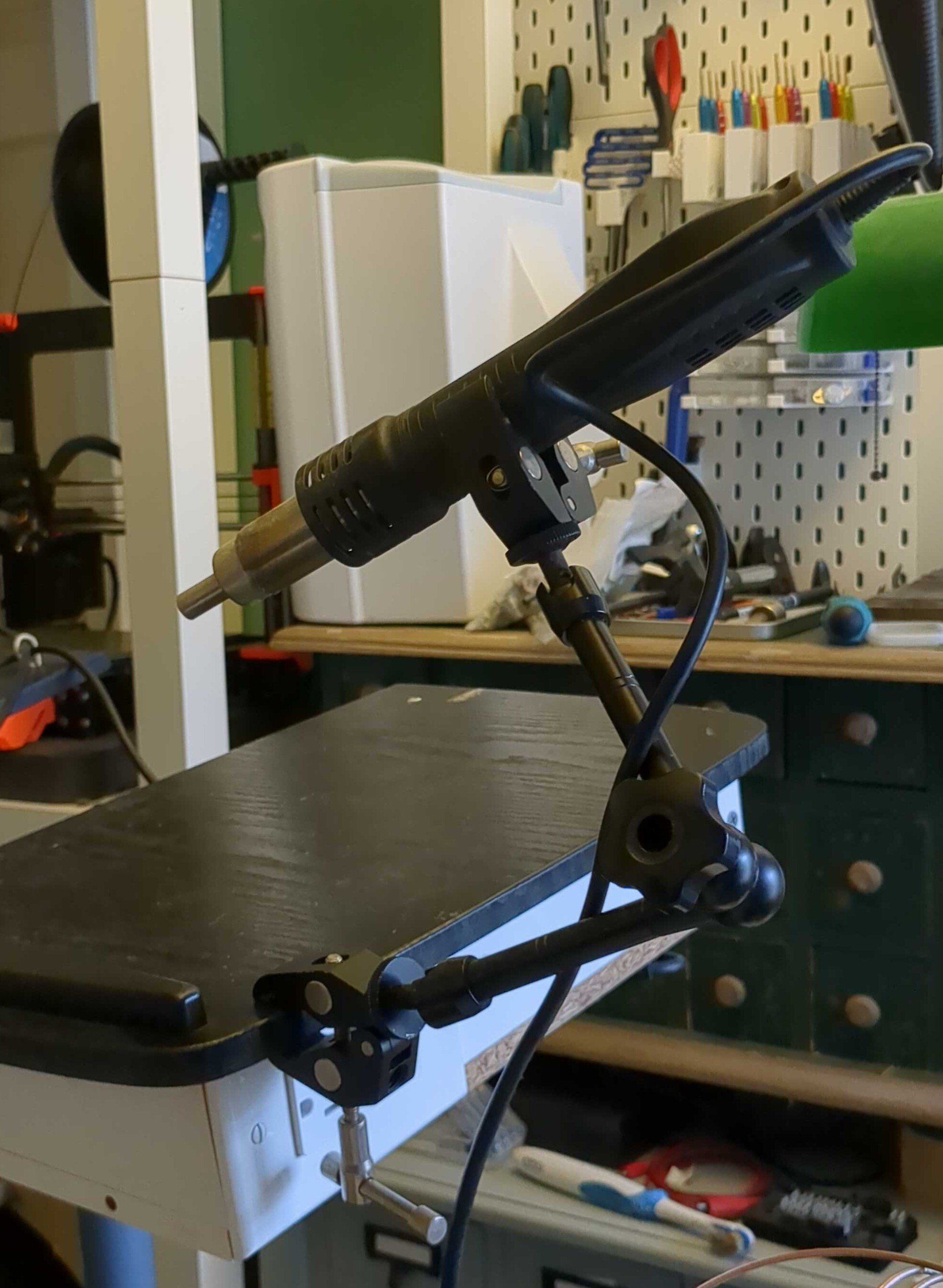
A basic cheap hotplate from a thrift store is helpful for preheating too, even one that is only for warning with no temperature adjustment.
I have a roll of very low temperature solder that has high bismuth content. It is not to solder with instead you use it lower the melting point of solder then wick it up . Was used at EMR Telemetry and when they were sold I was given a roll. Like a big roll of chip quik.
It is valuable to desolder things like ESP32s. The odds of lifting pads are slim with it too.
You just need a steady hand to be good at soldering


